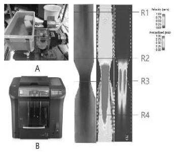
Fig. 1. (A) : Flow phantom motor system, (B) : 3D printer model, (C) : stenosis phantom computed flow dynamic mapping, R1~R4: interest regions